Worlds Most Useless Machine Rebuild
The Original Build
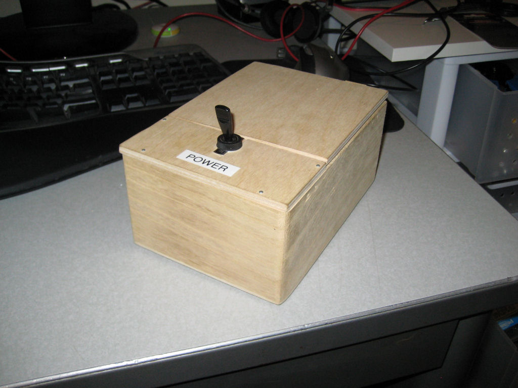
Back in 2009, I build my first copy of a "worlds most useless machine" from a video I found on wimp.com, it is no longer posted, which was a copy of the real original by Claude Shannon called the ultimate machine. The original box was built quickly over the course of one weekend and worked for a few weeks. However, the electronic circuit had a few flaws due to me trying to save costs. I was trying to power the servos and the electronics from the same batteries which caused some problems and ended up frying my microelectronic. 3 years later and I decided to revive the box and make some improvements to both the electronics and the operation of the box. With the original box, most people were skeptical when I handed it to them and told them to turn it On, they always wanted to open the lid first. So I decided to add a lock to the box, so they can't open it. The only thing they can do is turn on the switch, which adds to the suspense. It really is fun to watch people see the box for the first time.
Building the Box
The base box used in the prototype was a cheap wooden box purchased from Michaels Craft Stores. I replaced the lid with a small piece of 1/2" plywood that I cut to make the two halves. The side with the switch is nailed on while the flap side was attached with the boxes original hinges moved to the side. The servo mounts and battery holder are made out of craft balsa wood.
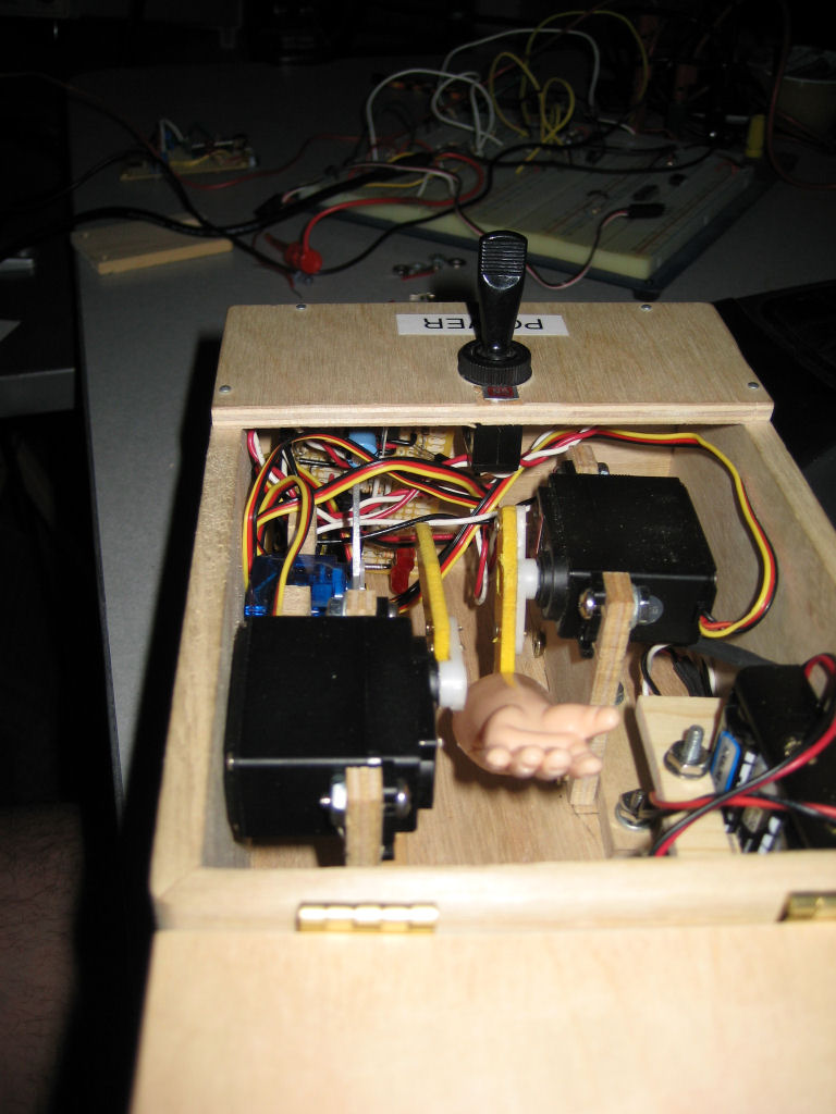
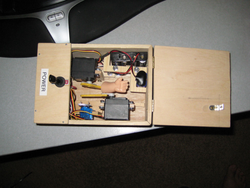
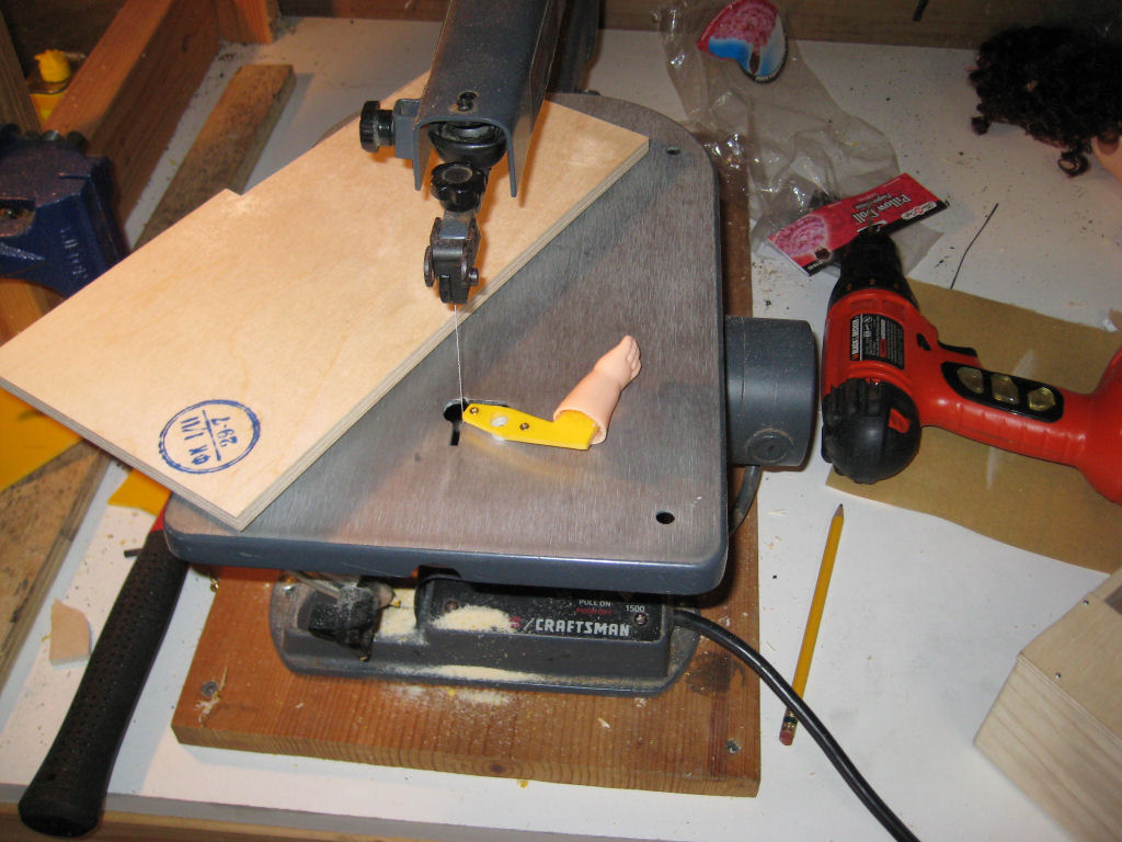
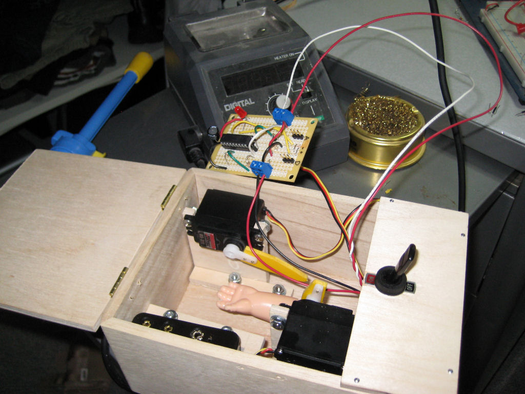
The Design for the arm attachment, made out of ABS plastic Sheet.
You can see the design of the lid arm which pushes up the lid.
Schematic and Design
Basic Logic Flow:
- User Turns On Power
- MicroController Powers On
- MicroController Turns on Solid State Relay that Latches on the Power Switch. The Microcontroller Turns on a second Solid State Relay which controls power to the servos.
- MicroController Opens the Lock
- MicroController Opens the Lid
- MicroController Moves the Arm Out
- Once the MicroController Detectes the switch has been turned off it then Moves the Arm In
- MicroController Closes the Lid
- MicroController Closes the Lock
- The MicroController then turns off both solid state relays which kills the power to itself and the servos.
Circuit Components:
Control Power, Circuit and Switch
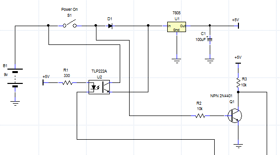
The Microcontroller and switch and powered from a 9V (B1) battery. Power flows from the battery through the switch to the input of a 7805 (U1) 5V voltage regulator. The 7805 supplies the 5V that are required to drive the MicroController and Solid State Relays (Opto Isolators). Once the switch has been turned on and the MicroController has received power a solid state relay (U2) is turned on to Latch on the power switch, effectively shorting out the switch to keep power on even if the switch is turned off. A Diode (D1) keeps power from flowing back from the solid state relay to the output of the switch. The Diode is needed so that the microcontroler can read the state of the switch, without it it would always have voltage potential because of the Latched Power. The State of the Switch which is 9V is also feed to a NPN Transistor (Q1). The transistor acts as a simple switch to switch a 5V source on and off so the MicroController can safely read the state.
Servo Power
The Hobby Servo's are powered from a 4 AA batteries (B2) supplying 6V's. The Micocontroller can turn the 6V power on and off using a Solid State Relay (Opto Isolator) (U4). The power is controlled via a relay so that no power is drained off the batteries from the Servo Control Circuits when the box is off.
Hobby Servos The Arm Servo (SRV3) and the Lid Servo (SRV2) are HiTec models HS-311 while the lock servo (SRV1) is a smaller HiTec HS-50, both purchased from ServoCity.com. Hobby Servos are a fraily inexpensive way to add control to your MicroController projects. They can easily be controlled via remote control or through a MicroController. Pololu Robotics & Electronics has a good article about the details of how the control signal works, I recommend reading it.
MicroController The MicroController (U3) I used for this project was a PicMicro 16F648A that I had in my parts supply. Its a little overpowered for this project, but still cheap enough to be used. The microcontroller sends the control signals to the hobby servos, Ability to control one status LED (D3), reads the input of the switch through Q1 and controls both Solid State Relays.
Full Shematic DumbMachine 20121125.pdf
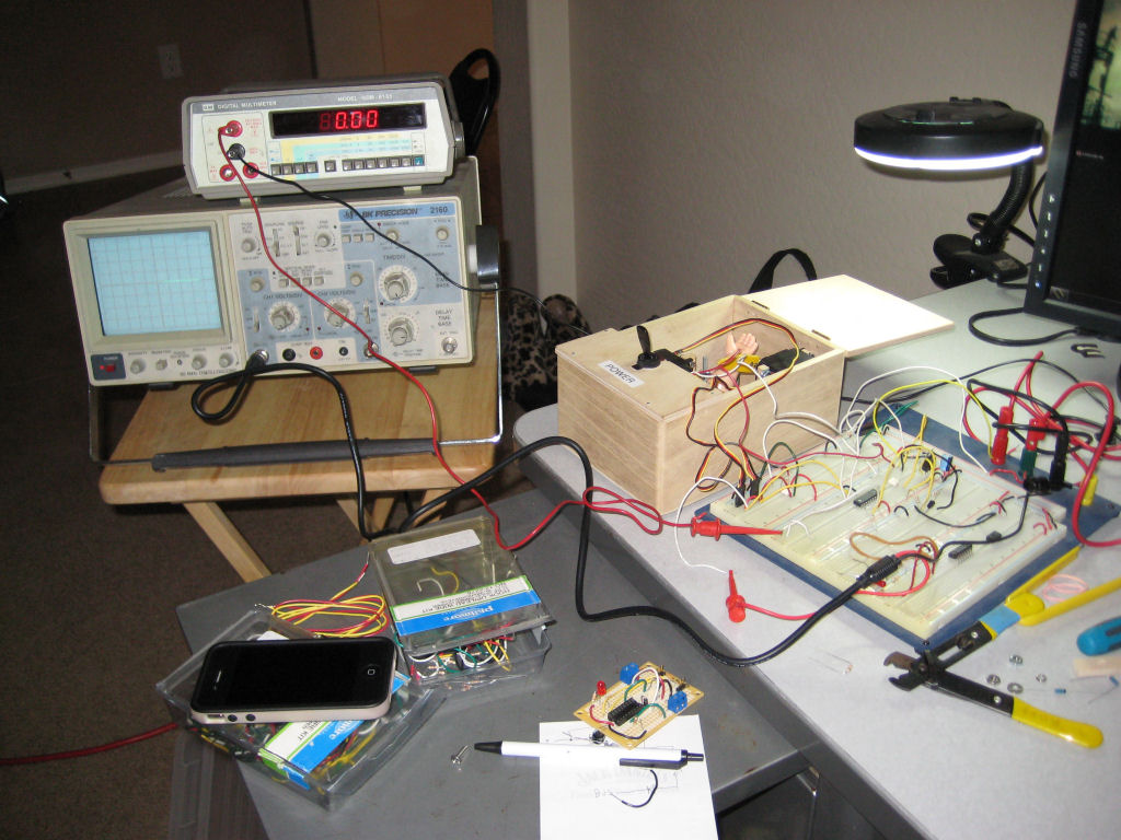
Soldering Up
I considered designing and ordering a Printed Circuit Board for this project but ended up using a prototype board from RadioShack because I didn't want to wait for the shipping time.

Microcontroller and Programming
I programmed the MicroController using MeLabs PicBasicPro Language and Compiler. I tried to document the code so that it can be easily read by someone with some MicroController Experience. The source code is licensed MIT, so feel free to copy it and modify it to make it your own.